simulationCases/coalescenceBubble-tag.c
Coalescence of Bubbles (Extended Version with Interface Tagging)
This is an optional extended version
of coalescenceBubble.c that provides
additional interface tracking using Basilisk’s
tag.h functionality.
Scientific Context
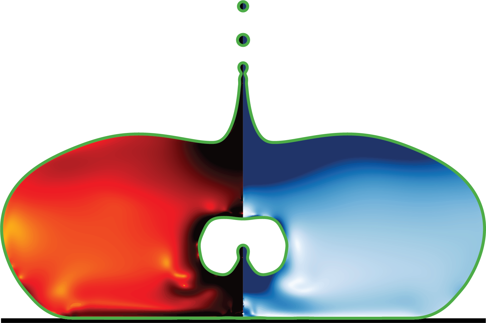
The simulations target coalescence-driven droplet injection into a parent bubble (Worthington jetting after capillary-wave focusing). This tagged version helps quantify geometry (poles, equatorial radius) while filtering out small satellite droplets that can otherwise bias diagnostics.
Key Differences from coalescenceBubble.c
- Uses
two-phase-tag.hinstead oftwo-phase.h(addsftag[]field) - Uses
tag.hto identify and track only the largest connected bubble region (filters out satellite droplets that may form during coalescence) - Outputs additional geometric measurements:
Re: Equatorial radius at center of massZNp: North pole position (positive x on axis)ZSp: South pole position (negative x on axis)
Log Output Format
Extended log columns:
i dt t ke Xc Vcm Re ZNp ZSp
(vs coalescenceBubble.c:
i dt t ke Xc Vcm)
Important Notes
- All production runs in this project use
coalescenceBubble.c, not this file - This file is provided for cases requiring detailed shape tracking
- Same MPI limitation as
coalescenceBubble.cdue todistance.hincompatibility
Usage
./coalescenceBubble-tag <OhOut> <RhoIn> <Rr> <MAXlevel> <tmax> <zWall>Author
Vatsal Sanjay [email protected] Physics of Fluids
Last updated: Jan 2026
#include "axi.h"
#include "navier-stokes/centered.h"
#define FILTERED
#include "two-phase-tag.h"
#include "navier-stokes/conserving.h"
#include "tension.h"
#include "distance.h"
#include "tag.h"
Simulation Parameters
MAXlevel: Maximum refinement level (set via command line)tsnap: Time interval for saving full snapshots (0.01)tsnap2: Time interval for logging diagnostics (0.0001)
int MAXlevel;

#define tsnap (1e-2)
#define tsnap2 (1e-4)
Error Tolerances
Adaptive mesh refinement is controlled by these error thresholds:
fErr: VOF volume fraction tolerance (determines interface resolution)VelErr: Velocity field tolerance (captures flow gradients)TOL: Position tolerance for geometric measurements
#define fErr (1e-3)
#define VelErr (1e-2)
#define TOL (1e-2)
Boundary Conditions
Left boundary (axis of symmetry): -
f[left]: No fluid at left boundary
(Dirichlet \(f=0\)) -
u.t[left]: No tangential velocity (no-slip
for azimuthal component)
f[left] = dirichlet(0.0);
u.t[left] = dirichlet(0.0);
Global Variables
Physical parameters and output configuration:
double tmax, MuRin, OhOut, RhoIn;
double Rr, zWall;
double Ldomain;
char nameOut[80], dumpFile[80];
Main Function
Initialize simulation parameters from command line and configure the domain.
int main(int argc, char const *argv[]) {
  if (argc < 7){
    fprintf(ferr, "Lack of command line arguments. Check! Need %d more arguments\n", 7-argc);
    return 1;
  }
Parse command-line arguments:
  MuRin = 1e-2;

  OhOut = atof(argv[1]);
  RhoIn = atof(argv[2]);
  Rr = atof(argv[3]);
  MAXlevel = atoi(argv[4]);
  tmax = atof(argv[5]);
  zWall = atof(argv[6]);
Domain size is calculated to fit both bubbles with sufficient margin.
  Ldomain = fmin(zWall+2.+2.*Rr+4.0, 16.);

  fprintf(ferr, "Level %d, Ldomain %g, tmax %3.2f, MuRin %3.2e, OhOut %3.2e, Rho21 %4.3f, Rr %f\n", MAXlevel, Ldomain, tmax, MuRin, OhOut, RhoIn, Rr);
Configure domain and fluid properties:
  L0=Ldomain;
  origin(-2.0-zWall, 0.0);
  init_grid (1 << (6));
Set fluid properties. Note:
ftag.sigma = 0 because ftag is
only used for tracking, not for surface tension
calculations.
  rho1 = RhoIn; mu1 = MuRin*OhOut;
  rho2 = 1e0; mu2 = OhOut;
  f.sigma = 1.0;
  ftag.sigma = 0.0;

  char comm[80];
  sprintf (comm, "mkdir -p intermediate");
  system(comm);
  sprintf (dumpFile, "restart");

  run();
}
Initialization Event
Load initial bubble shapes from pre-computed data
files. Both f and ftag are
initialized with the same interface shape.
event init(t = 0){
  if (!restore (file = dumpFile)){
    char filename[60];
    sprintf(filename,"InitialConditionRr-%3.2f.dat", Rr);

    char comm[160];
    snprintf (comm, sizeof(comm), "cp DataFiles/%s .", filename);
    if (system(comm) != 0) {
      fprintf(ferr, "Failed to copy initial-condition file '%s' from DataFiles/.\n",
              filename);
      return 1;
    }

    FILE * fp = fopen(filename,"rb");
    if (fp == NULL){
      fprintf(ferr, "There is no file named %s\n", filename);
      return 1;
    }
    coord* InitialShape;
    InitialShape = input_xy(fp);
    fclose (fp);
    scalar d[];
    distance (d, InitialShape);
    while (adapt_wavelet ((scalar *){f, d}, (double[]){1e-8, 1e-8}, MAXlevel).nf);
The distance function is defined at the center of each cell, we have to calculate the value of this function at each vertex.
    vertex scalar phi[];
    foreach_vertex(){
      phi[] = (d[] + d[-1] + d[0,-1] + d[-1,-1])/4.;
    }
We can now initialize the volume fraction of the
domain. Both f and ftag start
with the same interface.
    fractions (phi, f);
    fractions (phi, ftag);
    foreach(){
    u.x[] = 0.0;
    u.y[] = 0.0;
    }
    dump (file = dumpFile);
    static FILE * fp2;
    fp2 = fopen("InitialConditionStatus.dat","w");
    fprintf(fp2, "Initial condition is written to %s\n", dumpFile);
    fclose(fp2);
  }
}
Adaptive Mesh Refinement
Refine the mesh based on interface position and velocity gradients.
event adapt(i++){
  adapt_wavelet ((scalar *){f, u.x, u.y},
     (double[]){fErr, VelErr, VelErr},
      MAXlevel, MAXlevel-6);
}
Output Files
Save simulation snapshots at regular intervals.
event writingFiles (t = 0; t += tsnap; t <= tmax+tsnap) {
  dump (file = dumpFile);
  sprintf (nameOut, "intermediate/snapshot-%5.4f", t);
  dump(file=nameOut);
}

event end (t = end) {
  fprintf(ferr, "Level %d, Ldomain %g, tmax %3.2f, MuRin %3.2e, Oh2 %3.2e, Rho21 %4.3f, Rr %f\n", MAXlevel, Ldomain, tmax, MuRin, OhOut, RhoIn, Rr);
}
Auxiliary Fields for Geometric Measurements
posEq: Stores equatorial positions for radius calculationposPoles: Stores pole positions along the axis
scalar posEq[], posPoles[];Logging Event with Interface Tagging
This extended logging event performs connected component analysis to track only the main bubble, filtering out any satellite droplets that may form.
Interface Tagging Algorithm
- Copy
ftoftagat each timestep - Threshold
ftagto create binary field (\(f > 10^{-4}\)) - Use
tag()to identify connected components - Find the largest component (main bubble)
- Zero out
ftageverywhere except the main component
This ensures that geometric measurements (Re, ZNp, ZSp) only track the primary coalescing bubble, not small satellite droplets.
Geometric Measurements
Equatorial radius (
Re): Interface position at \(y = y_{COM}\) (radial extent at the center of mass height)North pole (
ZNp): Maximum \(x\) position where interface crosses axis (top of the bubble)South pole (
ZSp): Minimum \(x\) position where interface crosses axis (bottom of the bubble)
event logWriting (t = 0; t += tsnap2; t <= tmax+tsnap) {Copy current VOF field to tagging field:
  foreach(){
    ftag[] = f[];
  }
Connected Component Analysis
Tag all liquid regions with a threshold to avoid noise:
  scalar d[];
  double threshold = 1e-4;
  foreach(){
    d[] = (ftag[] > threshold);
  }

  int n = tag (d), size[n];
  for (int i = 0; i < n; i++){
    size[i] = 0;
  }
Count cells in each tagged region:
  foreach_leaf(){
    if (d[] > 0){
      size[((int) d[]) - 1]++;
    }
  }

  #if _MPI
  MPI_Allreduce (MPI_IN_PLACE, size, n, MPI_INT, MPI_SUM, MPI_COMM_WORLD);
  #endif
Identify the largest connected component (main bubble):
  int MaxSize = 0;
  int MainPhase = 0;
  for (int i = 0; i < n; i++){
    if (size[i] > MaxSize){
      MaxSize = size[i];
      MainPhase = i+1;
    }
  }
Zero out satellite droplets, keeping only the main bubble:
  foreach(){
    if(d[] != MainPhase){
      ftag[] = 0.0;
    }
  }
Compute Diagnostics
Calculate kinetic energy and center of mass using tagged field:
  double ke = 0., wt = 0., xCOM = 0., Vcm = 0.;

  foreach (reduction(+:ke) reduction(+:wt) reduction(+:xCOM) reduction(+:Vcm)){
    ke += 2*pi*y*(0.5*clamp(ftag[], 0., 1.)*(sq(u.x[]) + sq(u.y[])))*sq(Delta);
    xCOM += 2*pi*y*x*clamp(ftag[], 0.0, 1.0)*sq(Delta);
    Vcm += 2*pi*y*u.x[]*clamp(ftag[], 0.0, 1.0)*sq(Delta);
    wt += 2*pi*y*clamp(ftag[], 0.0, 1.0)*sq(Delta);
  }
  xCOM /= wt;
Equatorial Radius Calculation
Find interface position at height \(x = x_{COM}\) (within
tolerance TOL):
  int nEq = 0;
  double Req = 0.0;
  position (ftag, posEq, {0,1});
  foreach(reduction(+:Req) reduction(+:nEq)){
    if (x < xCOM+TOL && x > xCOM-TOL && posEq[] != nodata){
      Req += posEq[];
      nEq++;
    }
  }

  if (nEq != 0){
    Req /= nEq;
  } else {
    Req = 0.0;
  }
Pole Position Calculation
Find interface positions along the axis (\(y < TOL\)): - North pole: positive \(x\) intersection - South pole: negative \(x\) intersection
  double zNP = 0.0, zSP = 0.0;
  int nNP = 0, nSP = 0;
  position (ftag, posPoles, {1,0});
  foreach(reduction(+:zNP) reduction(+:nNP) reduction(+:zSP) reduction(+:nSP)){
    if (y < TOL && posPoles[] != nodata){
      if (posPoles[] > 0){
        zNP += posPoles[];
        nNP++;
      } else {
        zSP += posPoles[];
        nSP++;
      }
    }
  }

  if (nNP != 0){
    zNP /= nNP;
  } else {
    zNP = 0.0;
  }
  if (nSP != 0){
    zSP /= nSP;
  } else {
    zSP = 0.0;
  }
Write Log Output
  static FILE * fp;

  if (pid() == 0) {
    if (i == 0) {
      fprintf (ferr, "i dt t ke Xc Vcm Re ZNp ZSp\n");
      fp = fopen ("log", "w");
      fprintf(fp, "Level %d, Ldomain %g, tmax %3.2f, MuRin %3.2e, OhOut %3.2e, Rho21 %4.3f, Rr %f\n", MAXlevel, Ldomain, tmax, MuRin, OhOut, RhoIn, Rr);
      fprintf (fp, "i dt t ke Xc Vcm Re ZNp ZSp\n");
      fprintf (fp, "%d %g %g %g %g %g %g %g %g\n", i, dt, t, ke, xCOM, Vcm/wt, Req, zNP, zSP);
      fclose(fp);
    } else {
      fp = fopen ("log", "a");
      fprintf (fp, "%d %g %g %g %g %g %g %g %g\n", i, dt, t, ke, xCOM, Vcm/wt, Req, zNP, zSP);
      fclose(fp);
    }
    fprintf (ferr, "%d %g %g %g %g %g %g %g %g\n", i, dt, t, ke, xCOM, Vcm/wt, Req, zNP, zSP);
  }
Early Termination
Stop simulation when kinetic energy becomes negligible:
  assert(ke > -1e-10);
  if (ke < 1e-5 && i > 1000){
    if (pid() == 0){
      fprintf(ferr, "kinetic energy too small now! Stopping!\n");
      fp = fopen ("log", "a");
      fprintf(fp, "kinetic energy too small now! Stopping!\n");
      fclose(fp);
    }
    return 1;
  }
}